Designed by Oratek in Switzerland
Overview
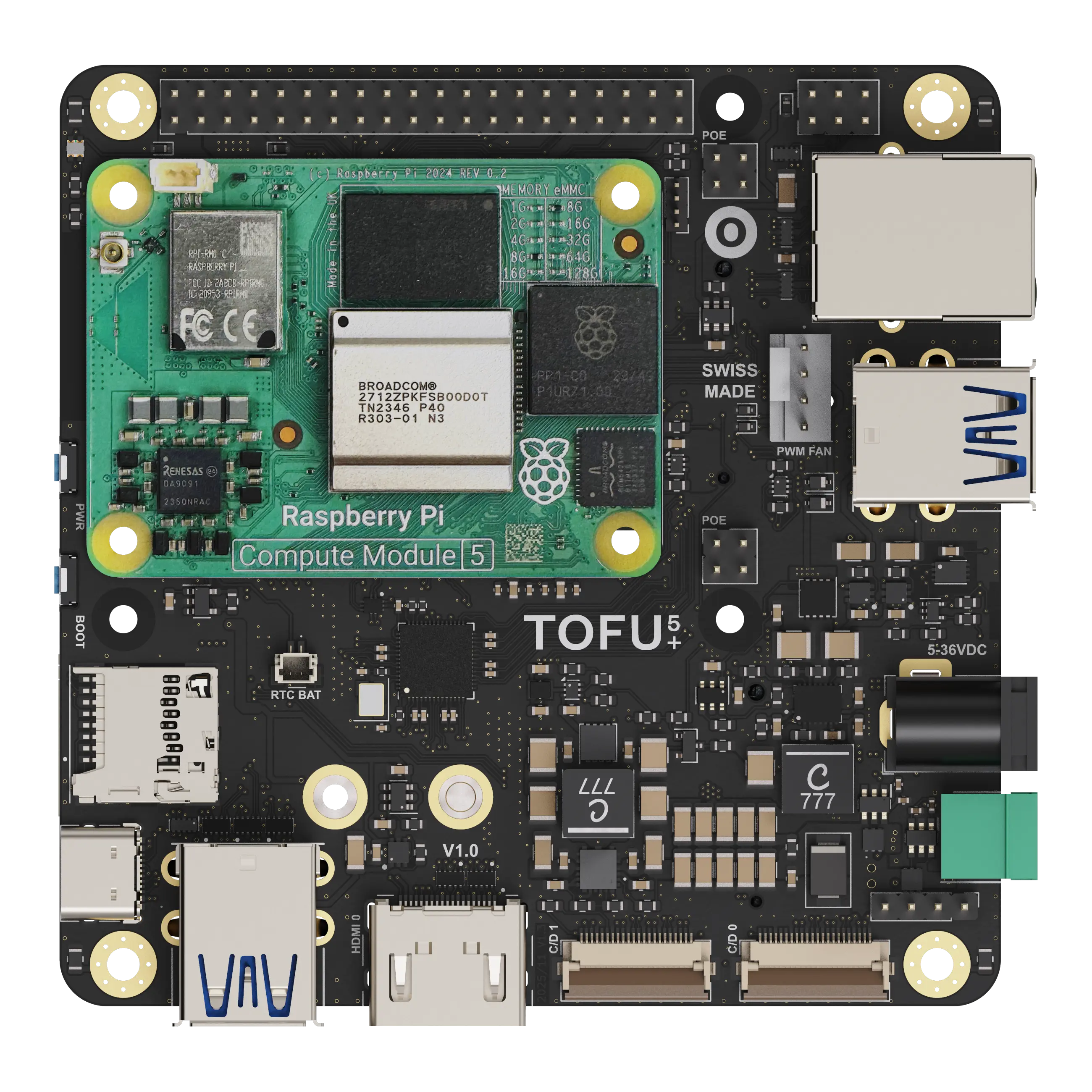
The TOFU5+ is the next-generation carrier board for the Raspberry Pi Compute Module 5 (CM5), designed to meet the evolving demands of industrial applications.
Built on the proven TOFU platform, the TOFU5+ enhances existing features, adds new functionalities, and maximizes the capabilities of the latest Compute Module. Maintaining the same compact footprint as the previous generation, this board introduces an updated and intelligent integration of displays, cameras, faster USB 3.0 ports, and two M.2 ports. These additions allow seamless use of SSDs and cellular modules, enabling a wide range of applications.
The TOFU5+ is engineered to operate over an extensive power range and offers numerous customization possibilities. With improved protection features, it delivers reliable performance across diverse and demanding scenarios.
Features
The size of the board is 9x9cm and its main features are :
- CM5 Assembly Slot
- Standard Raspberry Pi 40-Pin Heade
- 5-36V Input, 20W Shared 3.3V/10A and 5V/5A Power Supplies
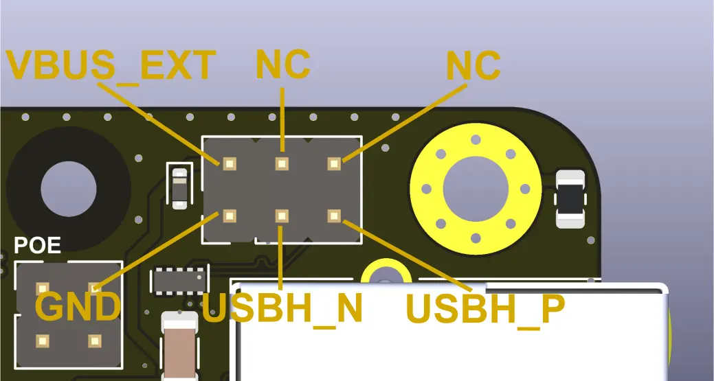
- Gigabit Ethernet Port, PoE/PoE+ Capability
- Compatible with both POE and POE+ Raspberry Pi HATs (spacer required)
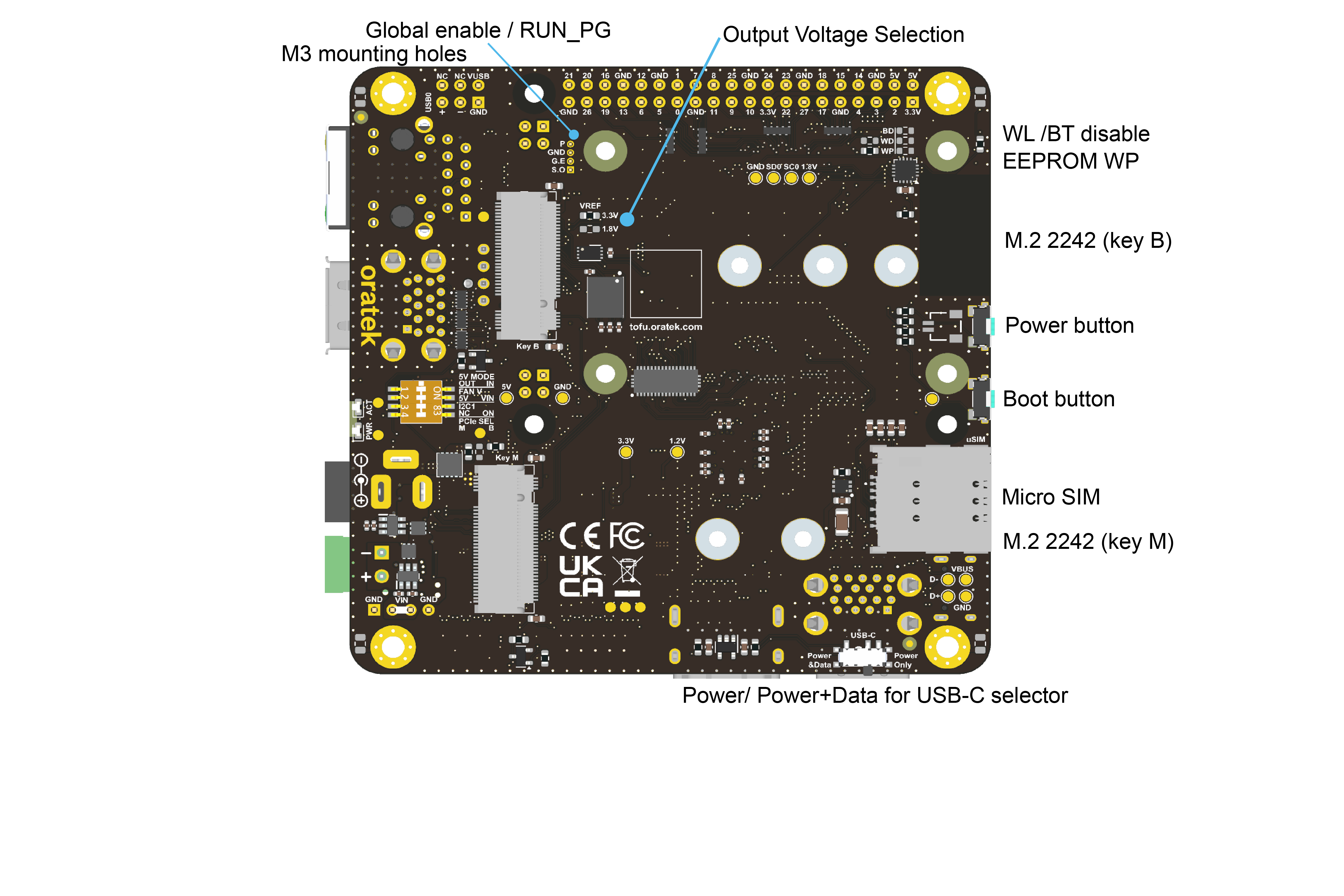
- M.2 Key M 2230/2242 Socket
- PCIe (Gen2 x1) Connectivity
- M.2 Key B 2230/2242/3042/3052 Socket
- USB3.0 or PCIe (Gen2 x1) Connectivity
- microSIM Card Holder
- eSIM Footprint
- 4x USB3.0 Type-A Ports
- Simple A Port Option [Molex 48405-0004 in place of 48406-0001]
- 1x USB2.0 Breakout Header
- 1x Full-Size HDMI Port
- 2x 4-Lane Camera (CSI)/Display (DSI) Hybrid Ports
- Barrel Jack and Terminal Block Power Inputs
- USB-C Power/Data Input with CM5-Enabled Power Delivery (PD)
- Up to 5V/5A Input
- USB 2.0 Connectivity
- Micro SD Card Slot for Lite Modules
- PWM Fan Port with Voltage Selection
- I2C Temperature Senso
- Real-Time Clock with external JST battery connector (same as Raspberry Pi 5)
- Cryptographic IC
- Red, Green, Blue I2C LED
- Activity, Power LEDs
- Boot Mode and Power Button
- 4x Switch Inputs
- PCIe Port Selection (Key B or M)
- I2C1 Enable for Second CSI/DSI Interface
- Fan Voltage Selection (5V or VIN)
- 5V Input/Output Configuration on 40-Pin Header
- Power Handling Capabilities
- Optional Main Power Watchdog
- 3.3V Power Shutdown for all Interfaces
- USB Power Shutdown
- Key B Network Card Wireless Disable and Shutdown
- ESD Protection on All Inputs/Outputs
- Standard Raspberry Pi and 4 Additional M3 Mounting Holes

Operating temperature
The CM5 is rated from -20°C to 85°C. All components on the TOFU board comply with this range.
Apart from connectors, all electronic components are rated for -40°C or below.
Layout
.webp)
Additional information
Tested compatibility list
NVMe SSDs (M.2 2242)
- KingSpec NE 2242, 128GB
- Western Digital PC SN520, 128GB
- Transcend MTE452T, 128GB
M key NVMe SSD (through adapter)
- Western Digital Blue SN550, 256GB, M.2 2280
- Western Digital Black SN750, 1TB, M.2 2280
- Samsung 970 Pro, 512GB, M.2 2280
Wireless/LTE/GPS modules (M.2 3042)
- Huawei ME906s-158
- Huawei ME936
- Sierra Wireless AirPrime EM7345
- SIMCom SIM7600G-H
Technical files
Mechanical
Electrical
Setup
Board features
To fully utilize the board possibilities, both USB ports and NVMe interfaces have to be enabled.
As indicated on the CM5 datasheet:
"The USB interface is disabled to save power by default on the CM4. To enable it you need to add the following to the config.txt file :"
dtoverlay=dwc2,dr_mode=host
NVMe support is also not enabled by default on Raspberry Pi OS. The command
sudo modprobe nvme-core
is needed, followed by a reboot to enable the NVMe kernel module.
More information on NVMe can be found on Jeff Geerling's CM4 review.
RTC Trickle Charging
To enable the trickle charging of the RTC when the CM5 is powered you'll need to add the following parameter in the '/boot/firmware/config.txt' file
dtparam=rtc_bbat_vchg=3000000
eMMC boot
To boot on eMMC, hold down the nRPIBOOT button while plugging the USB-C cable for flashing (no other power input). The USB cable will power the CM5 while it boots. You may release the button after having plugged the cable. Then, you need to run the rpiboot script. This can be done in two ways:
- If you have BalenaEtcher, open it. It will run the script in the background, and after a few seconds, your device will be recognized.
- Install rpiboot directly. For Linux/macOS, follow the instructions on their github page. For Windows, you can download the installer.
More information for flashing the eMMC can be found here.
Watchdog functions
The compute module behaves much like a Raspberry Pi 5. Thanks to this, one can use the same watchdog functions for reliability issues. You can have a look at diode.io for more information on how to use those. More information may also be found on this StackExchange thread.
SSD mounting
First, you need to partition the storage, following this tutorial from pidramble. Note that /dev/sda1 will most likely be replaced by /dev/nvme0n1.
An alternate possibility for mounting can be found on Raspberry Pi's website, here (with a formatted device).
A neat benchmark test can be run to find your SSD performance by running the command from pibenchmarks.com.
sudo curl https://raw.githubusercontent.com/TheRemote/PiBenchmarks/master/Storage.sh | sudo bash
This command has to be run in the disk location.
NVMe SSD boot
Raspberry Pi supports NVMe SSD booting, and the TOFU5+ board is the perfect companion for that! You may find more information on Raspberry Pi's documentation.
USB-C power/power+data configuration sliding switch / USB 2.0 breakout header
If a cable in plugged into the USB-C socket and sliding switch is on power+data position, the CM5 becomes a usb device (default) and its USB 2.0 bus is routed to the USB-C port.
If the sliding switch is in the power position, the USB-C port is used for power only and the CM5 USB 2.0 bus is routed to the USB 2.0 breakout header.
Network cards
M.2 network cards often use the USB line of the connector as interface. Remember to enable the USB interface, as mentioned above.
The tested cards work natively using Balena OS with Network Manager and Modem Manager being pre-installed. You will just have to set up a configuration file and it works straight out of the box (more details).
Another way is to manually install Network Manager and Modem Manager and configure it. This is not specific to the TOFU board but more general to Linux. A guide to get started can be found here.
I2C temperature sensor
I2C temperature sensor is based on the [MCP9808](https://ww1.microchip.com/downloads/en/DeviceDoc/25095A.pdf)
First, enable the I2C bus by adding the following parameter in the '/boot/firmware/config.txt' file
dtparam=i2c_arm=on
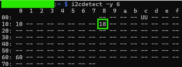
Use the following command to check if the I2C device is detected on the I2C0 bus:
i2cdetect -y 6
The device on address 0x18 shall be detected:
Clone the git repository with the example file.
git clone https://github.com/DcubeTechVentures/MCP9808.git
cd /MCP9808/Python/
Add missing parenthesis for the print functions at the end of MCP9808.py file
# Output data to screen
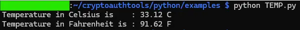
print ("Temperature in Celsius is : %.2f C" %ctemp)
print ("Temperature in Fahrenheit is : %.2f F" %ftemp)
Launch the script and observe the output for successful temperature retrieval
python MCP9808.py
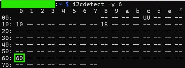
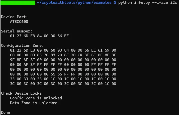
Cryptographic IC
Crpytographic IC is based on the ATECC608B
First, enable the I2C bus by adding the following parameter in the '/boot/firmware/config.txt' file
dtparam=i2c_arm=on
Use the following command to check if the I2C device is detected on the I2C0 bus:
i2cdetect -y 6
The device on address 0x60 shall be detected:
Then install the Official MicroChip CryptoAuthLib tools Library:
sudo apt install build-essential cmake libudev-dev libusb-1.0-0-dev libffi-dev libssl-dev git
git clone https://github.com/MicrochipTech/cryptoauthtools.git
cd cryptoauthtools/python/examples
pip install -r requirements.txt
Change the I2C address in the [info.py](https://github.com/MicrochipTech/cryptoauthtools/blob/master/python/examples/info.py) file at line 42 to 6
cfg.cfg.atcai2c.bus = 6
Launch the test script and observe the output for successful data retrieval
python info.py -i i2c
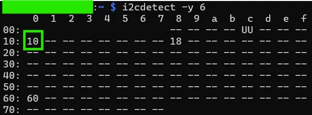
RGB LED
RGB LED functionnality is based on the 150066M153000 RGB LED and the I2C GPIO expander PCA9670.
First, enable the I2C bus by adding the following parameter in the '/boot/firmware/config.txt' file, then reboot
dtparam=i2c_arm=on
Use the following command to check if the I2C device is detected on the I2C0 bus:
i2cdetect -y 6
The device on address 0x10 shall be detected:
You can use the following command to update the P0, P1 and P2 output and drive the RGB LED.
Drive LED White
i2cset -y 6 0x10 0x00 0
Drive LED Purple
i2cset -y 6 0x10 0x00 2
Drive LED Blue
i2cset -y 6 0x10 0x00 3
Drive LED Green
i2cset -y 6 0x10 0x00 4
Drive LED Red
i2cset -y 6 0x10 0x00 6
Drive LED OFF
i2cset -y 6 0x10 0x00 7
Pin configurations
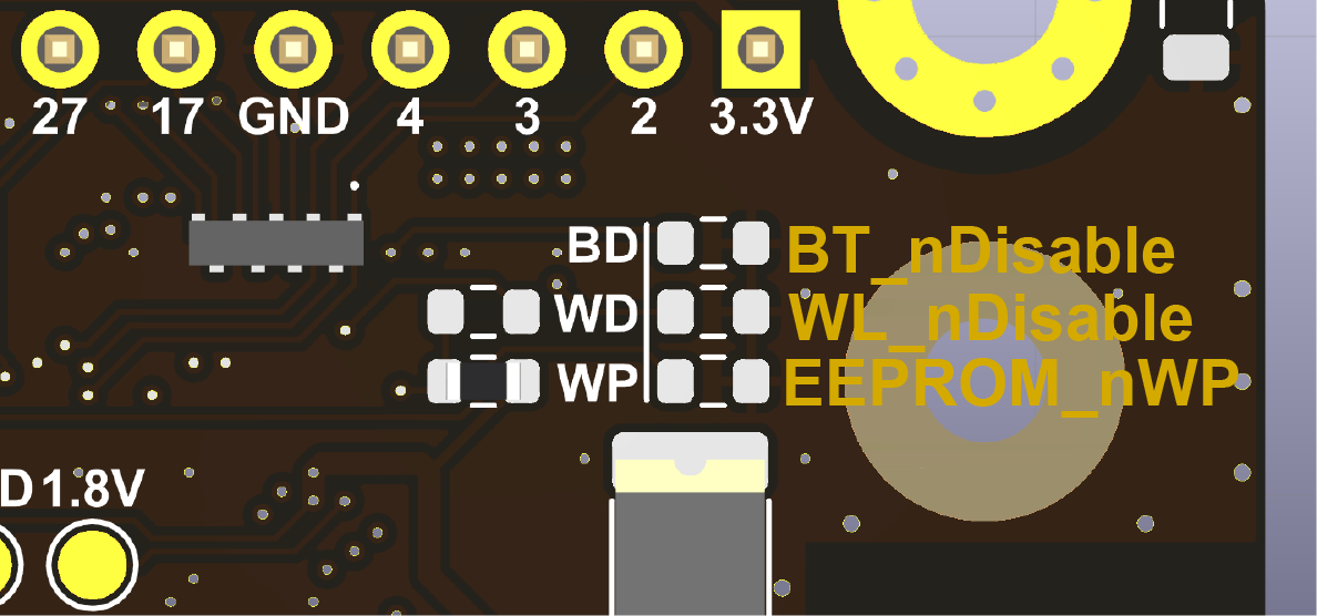
- WiFi Disable
- Bluetooth Disable
- EEPROM write protection

- GPIO output voltage selection, 3.3 V or 1.8 V. (populate only one resistor)

- Power button
- GND
- Global Enable
- Sync Out.
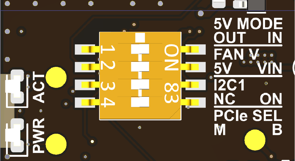
- PCIe Port Selection (Key B or M)
- (I2C1 Enable for Second CSI/DSI Interface)
- Fan Voltage Selection (5V or VIN)
- 5V Input/Output Configuration on 40-Pin Header
Warning
- Any external power supply used with the TOFU5+ Board shall comply with relevant regulations and standards applicable in the country of intended use.
- This product should be operated in a well-ventilated environment. If used inside a case, the case should not be covered and should allow for heat dissipation.
- Whilst in use, this product should be placed on a stable, flat, non-conductive surface, and should not be contacted by conductive items.
- The connection of incompatible devices to the TOFU5+ Board may affect compliance, result in damage to the unit, and invalidate the warranty.
- All peripherals used with this product should comply with relevant standards for the country of use and be marked accordingly to ensure that safety and performance requirements are met. These articles include but are not limited to keyboards, monitors, and mice when used in conjunction with the TOFU5+ Board.
- The cables and connectors of all peripherals used with this product must have adequate insulation so that relevant safety requirements are met.
Safety Instructions
To avoid malfunction or damage to this product, please observe the following:
- Do not expose to water or moisture, or place on a conductive surface whilst in operation.
- Do not expose yourself to excessive heat from any source.
- Take care whilst handling to avoid mechanical or electrical damage to the printed circuit board and connectors.
- Whilst it is powered, avoid handling the printed circuit board, or only handle it by the edges to minimise the risk of electrostatic discharge damage.
Resources
- Raspberry Pi Compute Module 5 datasheet
- Raspberry Pi Compute Module 5 IO Board datasheet
- General Raspberry Pi documentation
Customisation
Oratek is an engineering firm at earth therefore any customization or development based on the TOFU is not only a possibility but also a reality. In the past years, we have developed numerous custom development and we are happy to hear any request.
For any enquiry, please contact us
Declarations of Conformity
- RoHS Declaration of Conformity
- CE Declaration of Conformity
- FCC Declaration of Conformity
- UKCA Declaration of Conformity
Raspberry Pi is a trademark of the Raspberry Pi Foundation